On the way to prototyping my
ducted wind turbine design, there have been a few silly setbacks as usual with 3D printing, and that's before even mentioning how awkward part sourcing is when no one supplier ever has everything you need, and I end up forced to waste postage on a few orders just to get electronics to build a data-logging controller with. Also I'm writing this for a second time since Blogger ate my post by erroneously bringing up a blank workspace one morning after I was 90% through this post, and saving over it before I could close the tab. Unlike those lovely
etherpads, there was no writing history to revert back to.
I've brought this reprap to its working limits in a couple of different ways over the last few weeks, firstly with a bespoke drill-guide that I made in a similar way to the
dremel cutting kit only super-sized so as to allow a cheap hammer drill to make nicely perpendicular holes in the absence of a drill press.
A trouble with this print is its huge width compared to the narrow surface area actually in contact with the print surface, which meant that, being a PLA prototype, it could barely adhere to the kapton-taped surface strongly enough to stay down. When some overhanging edges started to curl up slightly, the resulting light collisions with the extruder head caused the wider of two parts to start lifting up off the printbed with an audible crack. I found a quick fix to keep that part in place before the whole surface dislodged.
 |
| Bulldog clips and small allen keys were handy, so they held the part down. |
This print was eventually successful, but not before another limit in size surprised me.
There is a slight complication in the build volume with this triangular-prism shaped frame, depending upon how the extruder is fitted; normally the greatest available Z-height is clearly limited by when the tallest part of the extruder reaches the top bars, or in my case when part of the extruder motor reaches the control-board mounting plate.
 |
| Above centre: on the top layer of the smaller part of this print, 75mm up, the motor passed so close to the frame that I could no longer see the gap. I removed one of the board's mounting blocks at that corner when I saw it get close, or it would already have collided. |
This complication arose since the extruder motor was mounted at the positive end of the x-axis, so that when it was at positions close to that end of the x-axis, height was limited by the extruder motor potentially moving through space occupied by one of the frame bars at 60°, and because there currently isn't an option in host software such as printrun to only allow prints to fit within a space more complicated than a cuboid.
When starting to test I learned a simple lesson about the J-Head Mk.IV hot-end: don't ever forget to turn on a cooling fan when running PLA through it.
 |
| Result of no cooling: molten PLA worked its way up to plug the heat barrier. |
Thankfully this hot-end is very easy to dis-assemble, and as soon as I dug a bit of that PLA out of the top, by removing a chunky set-screw from the end with an allen key, the remaining clogged PLA practically popped out with a still-warm PTFE sleeve.
 |
| That black set-screw I think is about M8 size, and is a clever way of keeping the sleeve compressed while having a gap for filament to pass through. |
So I gave printing on cardboard another try, this time trying to print a plant-holding part of my rotary hydroponics kit, but something else went wrong in the first layer when it seemed that the hot-end couldn't stay up at melting temperature.
 |
| Adhesion to inside-of-cereal-box cardboard was initially great until this. |
After testing the heater and checking around with a multimeter to figure out why it was completely failing to heat up anymore, I realised that an electronic part had blown out that I would never have expected to do so before.
 |
| This nearly-new wire-wound heating resistor that came installed with the new hot-end somehow ruptured under normal operating conditions. 'W21 5PS' is printed on the opposite side. |
While it's a cheap part to replace, I decided that I wasn't going to wait over a weekend to get a new one, so I tried taking the working resistor out of my old hot-end that was still lying around for spares, as you can see it in the top-left of the last picture. On dis-assembling the old heater block however, I found out that putting cheap thermal paste on one of those resistors isn't a great idea, as it had turned into a fine grey dust that got everywhere after a year of repeated heating.
There was still another problem with fitting my old heating resistor though.
 |
| It didn't fit. |
 |
| But a bit of aluminium foil quickly solved that. |
My quick solution may not give a perfect fit, but at least it was back up and running so that I could continue testing PLA onto cardboard.
First I tried a wide part that would test the warping problem that I had with paper. For this I used a z-motor bracket from Prusa's Mendel iteration 2 repository, aligned flat along the build plate. I quickly saw again something else that I needed to improve in my printer:
 |
| Overhanging corners of PLA start to curl up slightly during printing. |
Although I clearly needed to add some cooling to improve the quality of slight overhangs in PLA, at least the bottom surface warp wasn't bad.
 |
| Pretty good actually, very near parallel. |
My solution to cooling was to hook up a fan that I'd salvaged from the case of an old discarded mac computer with some spare wire and old
bolt-on PLA bushings.
 |
| Fan in foreground with another z-motor bracket cooling down. |
The result of a re-test was much better:
 |
| So good that it would fit right away without any reaming. |
However, the wiring for this new fan was a bit messy, being shoved into the screw terminal plug for my motherboard at one end, with jumper wires at the other end (visible above), and I resolved to tidy up some of the growing mess that was the wiring of my printer (the x-carriage fan was plugged in by a terminal strip that I turned back-to-front whenever I wanted to switch it off, while I had used a bit of screw terminal block to connect 240V mains wires to a 12V power supply, which were one misplaced hand-tool away from a nasty shock - all in all, an embarrassment) with a power switchbox using some nice chunky switches that I had lying around.
 |
| A large print of my custom switchbox design. |
The print didn't go badly until the last few layers when the extruder jammed just as it was about to print some holes for the lid to hinge around. Thankfully it wasn't an exploding resistor this time, but a far easier-to-replace part.
I had heard a little snap from that region earlier and not thought much of it, which was silly, but at least it shouldn't happen in future. It seems that printing a few wide things across cardboard isn't a very wise idea though as shown here:
 |
| Warp was pretty bad this time. |
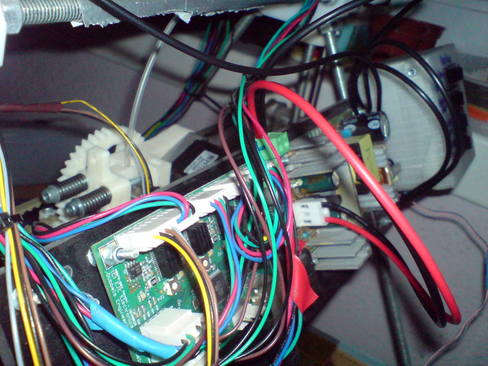
I eventually got it all together though, making my power wiring somewhat neater and making it easier to switch fans on and off, even if I still can't have the fans controlled by the old gen6 motherboard.
 |
| My electronics mounting board is now about as crowded as it can get. |
After testing wide-object warp (the badly warped box seemed to be more due to adhesion loss than flexibility in the cardboard), I wanted to check out how well a tall object would print, so I placed a couple of the same motor brackets in their usual vertical alignment along with a few bar clamps to also see how well small things would do here.
 |
| I also set slic3r to code in a line of skirt material around each object individually rather than around the whole print at the start, hoping that this might help to stop edges peeling up. |
The small bar-clamps turned out fine, but the motor brackets not so well due to there being enough flexibility in the cardboard for them to get knocked back and forth by the extruder head.
 |
| These definitely weren't usable straight off the printer. |
Since the small parts were fine, I tried again with more, this time with the both the bar clamps and
geodesic dome connector ball-joints that I
had trouble with last time.
 |
| Oh, and a pulley. |
That worked exceptionally well, so I did some more.
 |
| These were still great, even though the parts spanned a lot of the cardboard area, and they pop off cleanly and easily by simply bending the card after printing. |
I almost forgot to mention, a friend kindly picked up a sheet of cut glass for me at our nearest glaziers (about 100 miles away), and since then print quality with PLA has been unmatched on my heated bed - adhesion is just great every time so long as the glass is clean.
 |
| Bottom surfaces are almost perfectly flat too, with a very shiny finish. |
So cardboard seems to be a useful cheap temporary surface, but nothing can compare to a glass surface if you can get access to it (cost was not a problem for me - about tree fiddy - but distance was). One obvious disadvantage though is the extra weight (about 300g) that this 3mm plate adds to the y-carriage, which puts a further limit on the top speed that this printer can run at, due to risks of the plate becoming loose or increased backlash at high speeds. As a small technical point, I've measured temperature on top of the glass plate at about 65°C while the aluminium plate is at 72°C.
I've also seen people on the reprap IRC saying that they have successfully printed ABS onto a glass surface by using a thin layer of
PVA (a common wood glue, which forms
a water-soluble biodegradable polymer that has also been used as removable support material in dual-extrusion printers). This is great since it means that people can stop using polyimide as a print surface, since it is clearly unsustainable as a thermoset that loses its 'stick' in a number of months. There is a slight paradox there though since ABS as our main heat-resistant prototyping material is itself an unsustainable feedstock as we don't have any way to produce it that doesn't use fossil oil. This I'll be looking at solving through over-engineering soon - by sand-casting parts in recycled aluminium from PLA forms.
After all that, I've finally prepared a couple of test pieces to see how strong the mounting points in my wind turbine design can be, meanwhile it looks like the studding&nuts used as cheap leadscrews on my z-axis are finally wearing out badly from friction. I'll update with details when I have some results from strength tests, as this post has become long enough and I have a few other things to be doing first.


For room temp printing with PLA scotch blue painters tape worked best for me. Wth heatbed (at 60 deg C) dilute pva glue over glass working well too.
ReplyDelete